The Complete LC-3 Execution Lifecycle: From Assembly to Execution Traces A first-principles walkthrough of a Rust-based LC-3 VM — from two-pass assembler to execution cycles, and laying the theoretical groundwork for zkVM traces.
- Filed under
- systems-programming
- on
- April 2nd, 2026 .
- Apr 2026
From Source Text → Binary Object → Memory → CPU Registers
Follow Along with the Code
Clone the repository and experiment alongside this guide for a deeper understanding.
🔗 Repository: mahantybiplab/LC-3-Rust
If you want to understand how execution traces work in modern Zero-Knowledge VMs (zkVMs), you have to start at the bare metal.
In this deep dive, we are going to follow a single program through its entire lifecycle using a custom Rust-based LC-3 Virtual Machine. We will watch it transform from human-readable text into a binary object file, get loaded into virtual memory, and finally execute cycle-by-cycle in the CPU’s registers. At the end, we’ll connect the dots and show how these fundamental CPU cycles form the basis of zkVM execution traces.
The Anatomy of Our Virtual Machine
A Virtual Machine, in this context, is a software simulation of physical hardware — every wire, register, and memory slot modelled as a data structure. Because it isn’t a physical chip, we call it “virtual.” From a practical perspective, it lets us safely run LC-3 programs in an isolated software environment.
Our LC-3 VM has exactly two components: memory and registers. Here is how they relate to each other and to the instructions that flow through them:

A compiled instruction — say, 0001 111 001 0 00 101 — gets loaded into memory at address x3000. When the CPU fetches it, the first 4 bits (0001) identify the opcode (ADD), which is matched against the instruction set. The matched operation then reads from and writes to the registers. That arrow from memory → opcodes → registers is the entire execution loop in one picture.
1. Memory — The Warehouse
A flat array of 65,536 slots (x0000 to xFFFF), each holding a 16-bit value. It stores everything side by side in the same address space: your program’s instructions, string data, and variables.
Not all of that space is yours to use, though. The LC-3 reserves specific regions for the operating system, interrupt handling, and device I/O:
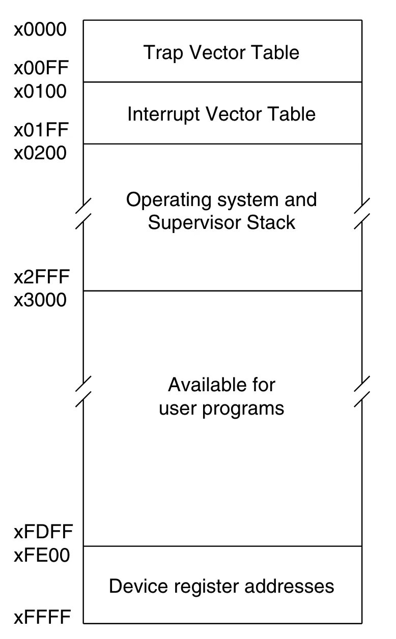
The regions matter for our VM:
-
x0000–x00FF— Trap Vector Table. Each address holds the starting address of a system call routine (PUTS,GETC,HALT, etc.). -
x0100–x01FF— Interrupt Vector Table. Addresses for hardware interrupt handlers. -
x0200–x2FFF— OS and Supervisor Stack. Reserved; your program must not touch this. -
x3000–xFDFF— User program space. This is where our loader writes the.objfile, and why.ORIG x3000appears at the top of every LC-3 assembly program. -
xFE00–xFFFF— Device register addresses (memory-mapped I/O).xFE00isKBSR(keyboard status) andxFE02isKBDR(keyboard data). Reading these addresses triggers hardware interaction rather than returning ordinary memory values.
Why 65,536 slots?
Because the LC-3 uses 16-bit addresses. A 16-bit address can express distinct values (x0000 through xFFFF). That means you can point at — at most — 65,536 different memory locations.
So the total memory capacity is:
- Why it’s needed: The CPU needs a place to hold far more information than it can keep close to itself. The entire assembled
.objfile is written here before a single instruction executes. - The catch: The CPU cannot do arithmetic directly on values in memory. It must first copy them into registers, operate there, and write the result back to a register or to a memory address — depending on whether the instruction is an
ADD(register result) or anST/STI(store result back to memory).
2. Registers — The Workbench
The CPU’s ultra-fast, immediately accessible workspace. Physically, think of registers as a type of memory that’s much closer to the CPU than RAM. The LC-3 has 8 general-purpose registers (R0–R7), each holding one 16-bit value, plus two special-purpose registers:
-
The Program Counter (
pc): Holds the memory address of the next instruction to fetch. After every fetch, the CPU increments it by 1 automatically. Branch and jump instructions work by overwriting it — which is how loops and conditionals are possible in hardware. -
The Condition Flags (
cond): Every time a value is written into a general-purpose register, the CPU records whether that value was Negative (N), Zero (Z), or Positive (P). Branch instructions inspect this flag to decide whether to jump or fall through. Only one flag is live at a time — writing to any register immediately overwrites the previous one. -
Why it’s needed: All arithmetic and logic in LC-3 happens exclusively between registers.
ADD R4, R2, R3adds whatever is currently in R2 and R3 — not raw values from memory. -
The constraint: With only 8 general-purpose registers, you are always juggling. Needing a 9th value means spilling something back to memory first.
In Rust, the entire physical reality of our LC-3 is two structs:
pub struct Registers {
    pub r0: u16,   // \
    pub r1: u16,   //  |
    pub r2: u16,   //  |
    pub r3: u16,   //  | general purpose (R0–R7)
    pub r4: u16,   //  |
    pub r5: u16,   //  |
    pub r6: u16,   //  |
    pub r7: u16,   // /
    pub pc: u16,   // program counter
    pub cond: u16, // condition flags: N / Z / P
}

pub struct VM {
    pub memory: [u16; 65536], // 64K × 16-bit slots = 64 × 1,024 × 16 bits = 65536 × 16 bits =  1,048,576 bits = 128 K
    pub registers: Registers,
}
Every mechanism in the sections that follow — the loader(the code in main.rs that reads the .obj file and writes each 16-bit word into vm.memory starting at x3000), the fetch-decode-execute loop, the ASCII conversion, the branch logic — is ultimately just reads and writes to these two structs.
The Program Under Study
add.asm
.ORIG x3000

; =====================================
; 1. GET THE FIRST INPUT
; =====================================
LEA R0, PROMPT1       ; Load address of PROMPT1 string into R0
PUTS                  ; Print the string (TRAP x22)
GETC                  ; Wait for keypress → result in R0 (TRAP x20)
OUT                   ; Echo the typed char (TRAP x21)
LD  R1, ASCII_NEG     ; R1 ← -48 (0xFFD0 in two's complement)
ADD R2, R0, R1        ; R2 = R0 − 48  (ASCII digit → integer)
LD  R0, NEWLINE       ; Load '\n' character
OUT                   ; Print newline

; =====================================
; 2. GET THE SECOND INPUT
; =====================================
LEA R0, PROMPT2
PUTS
GETC
OUT
ADD R3, R0, R1        ; R3 = R0 − 48  (ASCII digit → integer)
LD  R0, NEWLINE
OUT

; =====================================
; 3. DO THE MATH (SHOWING BOTH ADD MODES)
; =====================================
ADD R4, R2, R3        ; MODE 1 — REGISTER:  R4 = R2 + R3
ADD R4, R4, #2        ; MODE 2 — IMMEDIATE: R4 = R4 + 2 (baked into bits!)

; =====================================
; 4. PRINT THE RESULT
; =====================================
LEA R0, RESULT_STR
PUTS
LD  R1, ASCII_POS     ; R1 ← +48 (0x0030)
ADD R0, R4, R1        ; R0 = R4 + 48  (integer → ASCII char)
OUT
LD  R0, NEWLINE
OUT
HALT                  ; TRAP x25

; =====================================
; DATA SEGMENT
; =====================================
PROMPT1     .STRINGZ "Enter 1st digit: "
PROMPT2     .STRINGZ "Enter 2nd digit: "
RESULT_STR  .STRINGZ "Sum plus 2 is: "
NEWLINE     .FILL x000A    ; ASCII '\n'
ASCII_NEG   .FILL xFFD0    ; −48 in two's complement
ASCII_POS   .FILL x0030    ; +48
.END
This program reads two single-digit numbers from the keyboard, converts them from ASCII to integers, adds them using both ADD modes (register and immediate), converts the result back to ASCII, and prints it. Walking through its full lifecycle reveals every major mechanism of the LC-3 architecture.
Phase 1 — The Assembler: Text → Binary
Before the CPU can execute our program, the human-readable text must be converted into a flat, machine-readable binary object (.obj) file. This is the assembler’s job. However, it cannot translate the file in a single top-to-bottom read-through. Why? Because instructions at the top of our code (like LEA R0, PROMPT1) refer to labels that haven’t been defined yet. To solve this “forward reference” problem, the assembler processes the source code in exactly two distinct passes.
The assembler translates the .asm source into a .obj binary in exactly two passes.
Pass 1: Building the Symbol Table
The assembler’s only job in Pass 1 is to scan every line, maintain a Location Counter (LC) starting at the .ORIG address, and record the address of every label it encounters. No machine code is generated yet.
Each instruction and .FILL directive advances the LC by 1 word. .STRINGZ "text" advances by len(text) + 1 words (one word per character, plus a null terminator).
Instruction section (x3000 → x3018, 25 words):
| Address | Source Line | Words |
|---|---|---|
| x3000 | LEA R0, PROMPT1 | 1 |
| x3001 | PUTS (= TRAP x22) | 1 |
| x3002 | GETC (= TRAP x20) | 1 |
| x3003 | OUT (= TRAP x21) | 1 |
| x3004 | LD R1, ASCII_NEG | 1 |
| x3005 | ADD R2, R0, R1 | 1 |
| x3006 | LD R0, NEWLINE | 1 |
| x3007 | OUT | 1 |
| x3008 | LEA R0, PROMPT2 | 1 |
| x3009 | PUTS | 1 |
| x300A | GETC | 1 |
| x300B | OUT | 1 |
| x300C | ADD R3, R0, R1 | 1 |
| x300D | LD R0, NEWLINE | 1 |
| x300E | OUT | 1 |
| x300F | ADD R4, R2, R3 | 1 |
| x3010 | ADD R4, R4, #2 | 1 |
| x3011 | LEA R0, RESULT_STR | 1 |
| x3012 | PUTS | 1 |
| x3013 | LD R1, ASCII_POS | 1 |
| x3014 | ADD R0, R4, R1 | 1 |
| x3015 | OUT | 1 |
| x3016 | LD R0, NEWLINE | 1 |
| x3017 | OUT | 1 |
| x3018 | HALT (= TRAP x25) | 1 |
Data section (x3019 onward):
| Address | Label | Directive | Words (len + null) |
|---|---|---|---|
| x3019 | PROMPT1 | .STRINGZ "Enter 1st digit: " | 17 + 1 = 18 |
| x302B | PROMPT2 | .STRINGZ "Enter 2nd digit: " | 17 + 1 = 18 |
| x303D | RESULT_STR | .STRINGZ "Sum plus 2 is: " | 15 + 1 = 16 |
| x304D | NEWLINE | .FILL x000A | 1 |
| x304E | ASCII_NEG | .FILL xFFD0 | 1 |
| x304F | ASCII_POS | .FILL x0030 | 1 |
Hex Math Breakdown: Step-by-Step
Here is the column-by-column logic for the jumps in our Data Segment. Remember: in Hex, you carry over only after hitting 15 (F).
1. Adding 18 Words (x12)
Used to find the address after PROMPT1 and PROMPT2.
  x3019   (Start)
+ x0012   (18 words = 18 = 16+2 = (1×16^1)+(2×16^0) = x0012)
───────
x302B- Right column:
9 + 2 = 11. In Hex, 11 isB. - Second column:
1 + 1 = 2.
2. Adding 16 Words (x10)
Used to find the address after RESULT_STR.
  x303D   (Start)
+ x0010   (16 words = 16 + 0 = (1×16^1) + (0×16^0) = x0010)
───────
x304D- Right column:
D + 0 = D. - Second column:
3 + 1 = 4.
3. Sequential Fills (+1)
Used for single-word directives like .FILL.
x304D + 1 = x304E   (ASCII_NEG)
x304E + 1 = x304F   (ASCII_POS)
x304F + 1 = x3050   (End of Program)
Resulting Symbol Table after Pass 1:
┌────────────┬───────────┐
│   Symbol   │  Address  │
├────────────┼───────────┤
│  PROMPT1   │  x3019    │
│  PROMPT2   │  x302B    │
│  RESULT_STR│  x303D    │
│  NEWLINE   │  x304D    │
│  ASCII_NEG │  x304E    │
│  ASCII_POS │  x304F    │
└────────────┴───────────┘
Labels are just names for memory addresses. When Pass 2 sees LD R1, ASCII_NEG, it doesn’t look in the source — it looks up 0x3050 in this table.
Hexadecimal to Binary and Decimal Conversion
-
Hex to Binary
-
Each hexadecimal digit = 4 binary bits.
-
Convert each hex digit individually.
-
Hex to Decimal
- Use powers of 16 from right to left:
16³, 16², 16¹, 16⁰
Example: Convert x300A
Hex: x300A
Step 1: Hex → Binary
Convert each digit to 4-bit binary:
| Hex | Binary |
|---|---|
| 3 | 0011 |
| 0 | 0000 |
| 0 | 0000 |
| A | 1010 |
Binary result: 0011 0000 0000 1010
Step 2: Hex → Decimal
Calculate:
3×16³ + 0×16² + 0×16¹ + 10×16⁰
- 3 × 4096 = 12288
- 0 × 256 = 0
- 0 × 16 = 0
- 10 × 1 = 10
Decimal result: 12298
Use this mapping for fast conversion:
0=0000, 1=0001, …, 9=1001, A=1010, B=1011, C=1100, D=1101, E=1110, F=1111
Pass 2: Code Generation
Instead of manually encoding all 25 instructions, let’s zoom in on a few critical lines that demonstrate the LC-3’s core mechanics—starting with our two ADD modes.
Encoding ADD R4, R2, R3 — Register Mode (at x300F)
This is the register mode ADD, where both source operands come from registers. Identified by bit [5] = 0.
ADD Register Mode Format:
// Instruction Format
┌────┬─────┬─────┬───┬────┬─────┐
|0001│ DR  │ SR1 │ 0 │ 00 │ SR2 │
│15:12│11:9│ 8:6 │[5]│4:3 │ 2:0 │
└────┴─────┴─────┴───┴────┴─────┘
Opcode:    0001         (ADD)
DR:        100          (R4)
SR1:       010          (R2)
bit[5]:    0            (register mode)
bits[4:3]: 00           (unused)
SR2:       011          (R3)

Full word:  0001 100 010 0 00 011
Grouped:   0001 1000 1000 0011
Hex:       0x1883
Encoding ADD R4, R4, #2 — Immediate Mode (at x3010)
This is the immediate mode ADD. The literal 2 is baked directly into the instruction word itself. Identified by bit [5] = 1.
ADD Immediate Mode Format:
┌────┬─────┬─────┬───┬───────────┐
│0001│ DR  │ SR1 │ 1 │   imm5    │
│15:12│11:9│ 8:6 │[5]│   4:0     │
└────┴─────┴─────┴───┴───────────┘
Opcode:    0001         (ADD)
DR:        100          (R4)
SR1:       100          (R4)
bit[5]:    1            (immediate mode ← this single bit changes everything)
imm5:      00010        (+2, a 5-bit signed value)

Full word:  0001 100 100 1 00010
Grouped:   0001 1001 0010 0010
Hex:       0x1922
The critical contrast between both encodings:
Instruction      │ Hex    │ Binary
─────────────────┼────────┼──────────────────
ADD R4, R2, R3   │ 0x1883 │ 0001 1000 1000 0011
ADD R4, R4, #2   │ 0x1922 │ 0001 1001 0010 0010
                                    ↑
                              bit[5] flips 0 → 1
                              CPU reads bits[4:0] as imm5=2
                              instead of treating bits[2:0] as SR2
The trade-off: immediate mode saves a register load, but the literal is capped at 5 bits — a range of −16 to +15.
Encoding LD R1, ASCII_NEG — PCoffset9 Computation (at x3004)
LD loads a value from a memory address computed relative to the already-incremented PC. PC is already-incremented because in the LC-3 fetch–execute cycle, the CPU increments the PC during the fetch stage so it already points to the next instruction before the current instruction (like LD) is executed.
// In LC-3:
Effective Address = PC (after increment) + PCoffset
PCoffset9 = Target − (Instruction Address + 1)
           = 0x304E − (0x3004 + 1)
           = 0x304E − 0x3005
           = 0x0049  =  73  =  0b0 0100 1001
LD Format:
┌────┬─────┬─────────────────────┐
│0010│ DR  │     PCoffset9       │
│15:12│11:9│       8:0           │
└────┴─────┴─────────────────────┘
Opcode:    0010         (LD)
DR:        001          (R1)
Offset:    001001001    (73 = 0x49)

Full word: 0010 001 001001001
Grouped:   0010 0010 0100 1001
Hex:       0x2249
The ASCII Conversion Trick — Two’s Complement Addition
ADD R2, R0, R1 (where R1 = 0xFFD0 = −48) converts an ASCII digit to an integer. There is no special “convert” instruction — it’s pure two’s complement arithmetic.
If the user typed '5' (ASCII 53):
R0 = 0x0035  (53)
R1 = 0xFFD0  (−48)

0x0035 + 0xFFD0 = 0x10005
→ truncated to 16 bits = 0x0005 = 5  ✓
Why does 0xFFD0 equal -48?
0xFFD0 equal -48?First — why does MSB = 1 mean negative?
In a normal unsigned 16-bit number, every bit position carries a positive weight:
So 1111 1111 1111 1111 = . No negatives possible.
Two’s complement fixes this with one architectural decision: make the MSB’s weight negative.
That’s it. Every bit except the MSB keeps its positive weight. The MSB alone contributes . So any bit pattern with MSB = 1 starts at and adds the remaining bits back up — which is always a negative result.
Now, working out xFFD0 step by step
Step 1 — Hex to Binary Convert each hex digit to 4 bits:
| Hex | Binary |
|---|---|
F | 1111 |
F | 1111 |
D | 1101 |
0 | 0000 |
Full 16-bit string: 1111 1111 1101 0000
Step 2 — Check the Sign Bit
The MSB is 1. As established above, this means the number is negative and its MSB alone is already contributing . We now need to find the exact magnitude using the Flip and Add 1 shortcut — which is faster than computing the full weighted sum.
Step 3 — Flip All the Bits (NOT)
Invert every bit — 1 becomes 0, 0 becomes 1:
Before:  1111 1111 1101 0000
After:   0000 0000 0010 1111
Step 4 — Add 1
0000 0000 0010 1111
+                   1
= 0000 0000 0011 0000
The trailing 1111 + 1 ripple-carries left, turning all four bits to 0 and setting the next bit up.
Step 5 — Binary to Decimal
Only two bits are set in 0000 0000 0011 0000:
Result
The magnitude is 48. The original MSB was 1 (negative), so:
1. Direct weighted sum — use the rule literally:
2. Zero-sum check — add xFFD0 and +48. In two’s complement they must cancel to zero (carry discarded):
Drop the carry → 0000 0000 0000 0000 ✓
The reverse (integer → ASCII) via ADD R0, R4, R1 where R1 = 0x0030 (+48):
R4 = 0x000A  (10, the final sum)
R1 = 0x0030  (+48)

0x000A + 0x0030 = 0x003A  =  ASCII ':'
(Note: this program assumes single-digit inputs that sum to ≤ 9 before the +2. For sum = 7+1+2 = 10, the output is : — a known limitation for teaching purposes.)
Limitation — What happens when the sum exceeds 9?
The program converts a digit to ASCII by adding 0x0030 (+48) to the raw integer result. This works perfectly as long as the sum is a single digit (0–9):
| Sum | + 0x0030 | ASCII |
|---|---|---|
0 | 0x0030 | '0' |
5 | 0x0035 | '5' |
9 | 0x0039 | '9' |
But ASCII digits only occupy the range 0x0030–0x0039. The moment the sum hits 10 or above, you spill out of that range entirely:
| Sum | + 0x0030 | ASCII | Result |
|---|---|---|---|
10 | 0x003A | ':' | ❌ wrong |
11 | 0x003B | ';' | ❌ wrong |
12 | 0x003C | '<' | ❌ wrong |
For the inputs 7 + 1 + 2 = 10 in this program, the output is ':' instead of '10' — because the program has no logic to handle multi-digit results. Producing '10' would require splitting the integer into its tens digit (1) and units digit (0) and converting each separately, which involves division — an operation LC-3 has no native instruction for.
This is a deliberate simplification for teaching purposes. The program correctly demonstrates the ASCII ↔ integer conversion mechanic; it just assumes inputs small enough that their sum stays within 0–9.
The .obj File Structure
The assembled output is a flat sequence of 16-bit big-endian words. The first word is always the Origin Address — the only metadata the format contains.
File Offset │ Bytes (hex) │  Word (hex) │ Meaning
────────────┼─────────────┼─────────────┼──────────────────────────────
  0x00–0x01 │   30  00    │   0x3000    │ Origin address
  0x02–0x03 │   E0  19    │   0xE019    │ LEA R0, PROMPT1
  0x04–0x05 │   F0  22    │   0xF022    │ PUTS (TRAP x22)
  0x06–0x07 │   F0  20    │   0xF020    │ GETC (TRAP x20)
  0x08–0x09 │   F0  21    │   0xF021    │ OUT  (TRAP x21)
  0x0A–0x0B │   22  4B    │   0x224B    │ LD R1, ASCII_NEG
  0x0C–0x0D │   14  01    │   0x1401    │ ADD R2, R0, R1
  ...       │   ...       │   ...       │ ...
  (x300F)   │   18  83    │   0x1883    │ ADD R4, R2, R3  ← register mode
  (x3010)   │   19  22    │   0x1922    │ ADD R4, R4, #2  ← immediate mode
  ...       │   ...       │   ...       │ ...
  (x304E)   │   FF  D0    │   0xFFD0    │ ASCII_NEG = −48
  (x304F)   │   00  30    │   0x0030    │ ASCII_POS = +48
Big-endian means the Most Significant Byte is written first. For 0x224B, byte 0x22 hits the disk before 0x4B.
Phase 2 — The Loader: Disk → VM Memory
When cargo run -- examples/add.obj runs, the loader in main.rs executes:
let base_address = f.read_u16::<BigEndian>().expect("error"); // reads 0x3000

let mut address = base_address as usize; // = 12288

loop {
    match f.read_u16::<BigEndian>() {
        Ok(instruction) => {
            vm.write_memory(address, instruction); // memory[address] = word
            address += 1;                          // +1, not +2 — each slot is already u16
        }
        Err(e) if e.kind() == UnexpectedEof => break,
        Err(e) => panic!("failed: {}", e),
    }
}
vm.memory is [u16; 65535] — each element holds a full 16-bit word, so the address index increments by 1, not 2.
Memory state at key addresses after loading:
Address  │  Value (hex) │  Binary              │  Meaning
─────────┼──────────────┼──────────────────────┼───────────────────────
 0x3000  │   0xE018     │ 1110 0000 0001 1000  │ LEA R0, PROMPT1
 0x3004  │   0x2249     │ 0010 0010 0100 1001  │ LD R1, ASCII_NEG
 0x3005  │   0x1401     │ 0001 0100 0000 0001  │ ADD R2, R0, R1
 0x300F  │   0x1883     │ 0001 1000 1000 0011  │ ADD R4, R2, R3
 0x3010  │   0x1922     │ 0001 1001 0010 0010  │ ADD R4, R4, #2
 0x304E  │   0xFFD0     │ 1111 1111 1101 0000  │ −48  (ASCII_NEG)
 0x304F  │   0x0030     │ 0000 0000 0011 0000  │ +48  (ASCII_POS)
Memory Map: Post-Load Layout
 Address     Memory Contents        Segment
          .───────────────────.
          |    (Empty / OS)   |
          |───────────────────|
 x3000    |  0xE018 (LEA)     |  ◄── PC Start
 x3001    |  0xF022 (PUTS)    |   ▲
   ...    |       ...         |   │  INSTRUCTIONS
 x3017    |  0xF021 (OUT)     |   │  (25 words)
 x3018    |  0xF025 (HALT)    |   ▼
          |───────────────────|  ─── BOUNDARY
 x3019    |  'E' (0x0045)     |   ▲
 x301A    |  'n' (0x006E)     |   │
   ...    |       ...         |   │  DATA / STRINGS
 x304D    |  0x000A ('\n')    |   │  (55 words)
 x304E    |  0xFFD0 (-48)     |   │
 x304F    |  0x0030 (+48)     |   ▼
          |───────────────────|
          |    (Available)    |
          '───────────────────'
PC Initialization: Registers::new() hardcodes pc: PC_START where PC_START = 0x3000. The loader reads the origin word only to know where to write the program into memory. The PC is initialized independently by convention — they happen to agree on 0x3000.
Phase 3 — Execution: The CPU’s Fetch-Decode-Execute Loop
pub fn execute_program(vm: &mut VM) {
    while vm.registers.pc < MEMORY_SIZE as u16 {
        let instruction = vm.read_memory(vm.registers.pc); // FETCH
        vm.registers.pc += 1;                              // INCREMENT PC
        instruction::execute_instruction(instruction, vm)  // DECODE + EXECUTE
    }
}
We trace four cycles that capture every key concept in this program.
CPU Cycle 5 — LD R1, ASCII_NEG at x3004
Bitwise Shifting: << (Left) and >> (Right)
<< (Left) and >> (Right)Bitwise shifts move an entire sequence of bits left or right by a specified number of spaces. Think of it like a conveyor belt: bits are pushed in one direction, causing bits on one edge to fall off into the void, while empty spaces on the other edge are filled with new bits.
1. Left Shift (<<): The Multiplier
Shifting left pushes all bits to the left. The bits on the far left fall off and disappear, while new 0s are fed into the right side.
Mathematically, shifting left by spaces is the same as multiplying by .
Example: 3 << 2 (Shift the number left by spaces)
- Original:
0000 0011() - Shift 1:
0000 0110() - Shift 2:
0000 1100()
2. Right Shift (>>): The Divider
Shifting right pushes all bits to the right. The bits on the far right (the smallest values) fall off and are permanently lost. For unsigned integers, new 0s are fed into the left side.
Mathematically, shifting right by spaces is the same as integer division by (meaning remainders are dropped).
Example: 24 >> 3 (Shift the number right by spaces)
- Original:
0001 1000() - Shift 1:
0000 1100() - Shift 2:
0000 0110() - Shift 3:
0000 0011()
🛠️ Why we use them in the VM?
In computer architecture, you rarely use shifts for math; you use them to align data.
In your LC-3 VM, a 16-bit instruction contains multiple “fields” packed tightly together. To read the Destination Register (DR) sitting in bits [11:9], you have to move it to the end of the line before you can isolate it:
- Shift it:
instruction >> 9pushes the 16-bit word right by 9 spaces. The DR bits slide all the way down into the [2:0] slots. - Mask it: Now that the DR bits are at the end, you use
& 0x7to chop off all the higher bits, leaving you with just the exact Register ID!
Fetch
PC before:    0x3004
instruction:  vm.memory[0x3004] = 0x2249
PC after:     0x3005
Decode
0x2249 = 0010 0010 0100 1001
>> 12  = 0000 0000 0000 0010  = 2  →  OpCode::LD
Execute — ld(0x2249, vm)
1. Extract DR:
   0x2249 >> 9 = 17
   17 & 0x7    = 1  →  dr = R1 ✓

2. Extract PCoffset9:
   0x2249 & 0x1FF = 0x049 = 73
   sign_extend(73, 9): bit[8] of 73 = 0 → positive, no extension
   pc_offset = 73

3. Effective address:
   mem = 73 + 0x3005 = 0x304E

4. Read memory:
   vm.memory[0x304E] = 0xFFD0  (−48)

5. Write to register:
   R1 = 0xFFD0

6. Condition flags:
   0xFFD0 >> 15 = 1 → MSB is 1 → negative
   COND = NEG = (1 << 2) = 0x0004
State after Cycle 5:
R1   = 0xFFD0  (−48)
COND = 0x0004  (NEG)
PC   = 0x3005
The Hardware’s Helpers: Sign Extension & Condition Flags
To understand how a VM bridges the gap between small instruction components and 16-bit math, we have to look at two specific mechanisms: Sign Extension and the Condition (COND) Flags.
1. Sign Extension (sign_extend)
The Problem:
The LC-3 processor only knows how to do math on full 16-bit numbers. However, instructions often contain smaller numbers. For example, an ADD instruction in Immediate Mode only has 5 bits for the number. A LD offset only has 9 bits. How do we add a 5-bit number to a 16-bit register?
The Wrong Way (Zero Padding):
Imagine we want to add . In 5-bit Two’s Complement, is 11110.
If we just fill the remaining 11 bits with zeros so the ALU can process it, we get 0000 0000 0001 1110. In 16-bit math, that is . We completely destroyed the value!
The Right Way (Sign Extension): To keep the mathematical value identical while making the binary wider, we must look at the Most Significant Bit (MSB) of the small number (the sign bit) and copy it to fill all the new empty space.
- If MSB is
0(Positive): Pad with0s. - If MSB is
1(Negative): Pad with1s.
Example of Sign-Extending our 5-bit :
11110 copy the leading 1 1111 1111 1111 1110 (which is properly in 16-bit math).
sign_extend is called on every PCoffset9 and imm5 before arithmetic:
fn sign_extend(mut x: u16, bit_count: u8) -> u16 {
   if (x >> (bit_count - 1)) & 1 != 0 {
       x |= 0xFFFF << bit_count;
   }
   x
}
For a backward-jumping PCoffset9 like 0b1_1111_1100 (= −4 in 9-bit space):
Test sign bit: (0b1_1111_1100 >> 8) & 1 = 1  → negative!

0xFFFF << 9   = 1111 1110 0000 0000
x (9-bit)     = 0000 0001 1111 1100

x |= result:
  0000 0001 1111 1100
| 1111 1110 0000 0000
= 1111 1111 1111 1100  = 0xFFFC = −4 in i16  ✓
Without this, a backward branch offset of −4 would be misread as +508, sending the PC into garbage memory.
2. Condition Flags (COND)
The Problem:
A CPU has no memory of the past; it just blindly executes the instruction currently in the PC. So, how do you write an if statement or a while loop? The CPU needs a way to evaluate a value and make a routing decision.
The Solution: The Condition Flags act as a tiny, automatic “sticky note” that the CPU updates every time it writes data into a register. The LC-3 has three flags: N (Negative), Z (Zero), and P (Positive).
How it works:
- The Trigger: Any instruction that writes to a register (
ADD,AND,NOT,LD,LDI,LDR,LEA) triggers the flag update. - The Evaluation: The CPU looks at the raw 16-bit binary just before it goes into the register.
- If the MSB is
1, it sets the N flag. - If all 16 bits are
0, it sets the Z flag. - Otherwise, it sets the P flag.
- If the MSB is
- The Consumer: Branch instructions (
BR) do absolutely no math. They simply look at the “sticky note.” If you writeBRz(Branch if Zero), the CPU checks the Z flag. If it’s set, the PC jumps; if not, the PC just moves to the next line.
CPU Cycle 6 — ADD R2, R0, R1 at x3005 (ASCII → Integer)
Assume the user typed '5', so GETC placed R0 = 0x0035 (= 53).
Fetch
PC before:    0x3005
instruction:  vm.memory[0x3005] = 0x1401
PC after:     0x3006
Decode
0x1401 = 0001 0100 0000 0001
>> 12  = 0000 0000 0000 0001  = 1  →  OpCode::ADD
Execute — add(0x1401, vm)
0x1401 = 0001 0100 0000 0001

DR      = bits[11:9] = 010 = R2
SR1     = bits[8:6]  = 000 = R0
bit[5]               = 0   → REGISTER MODE
SR2     = bits[2:0]  = 001 = R1

val  = R0 + R1
             = 0x0035 + 0xFFD0
             = 0x10005
             → truncated to u16 = 0x0005 = 5

R2   = 0x0005
COND = POS = 0x0001
CPU Cycle 16 — ADD R4, R2, R3 at x300F (Register Mode)
Assume the user typed '3' for the second input, so after the same ASCII conversion, R3 = 3.
Fetch
PC before:    0x300F
instruction:  vm.memory[0x300F] = 0x1883
PC after:     0x3010
Decode
0x1883 >> 12 = 1 → OpCode::ADDExecute — add(0x1883, vm)
0x1883 = 0001 1000 1000 0011

DR      = bits[11:9] = 100 = R4
SR1     = bits[8:6]  = 010 = R2
bit[5]               = 0   → REGISTER MODE
SR2     = bits[2:0]  = 011 = R3

val = R2 + R3 = 5 + 3 = 8

R4   = 0x0008
COND = POS = 0x0001
CPU Cycle 17 — ADD R4, R4, #2 at x3010 (Immediate Mode)
The literal 2 is encoded directly inside the instruction word.
Fetch
PC before:    0x3010
instruction:  vm.memory[0x3010] = 0x1922
PC after:     0x3011
Decode
0x1922 >> 12 = 1 → OpCode::ADDExecute — add(0x1922, vm)
0x1922 = 0001 1001 0010 0010

DR      = bits[11:9] = 100 = R4
SR1     = bits[8:6]  = 100 = R4
bit[5]               = 1   → IMMEDIATE MODE ← key difference

imm5 extraction:
  0x1922 & 0x1F = 0b00010 = 2
  sign_extend(2, 5): bit[4] of 2 = 0 → positive, no extension
  imm5 = 2

val = R4 + imm5 = 8 + 2 = 10

R4   = 0x000A  (10)
COND = POS = 0x0001
Bit-level contrast of the two ADD cycles:
ADD R4, R2, R3  →  0x1883  →  0001 1000 1000 0011
ADD R4, R4, #2  →  0x1922  →  0001 1001 0010 0010
                                        ↑
                                    bit[5] = 1
                              CPU reads bits[4:0] as imm5 = 2
                              instead of treating bits[2:0] as SR2
Complete Execution Summary
Cycle │ Address │  Word   │ Op         │ Key Effect
──────┼─────────┼─────────┼────────────┼────────────────────────────────────
  1   │ x3000   │ 0xE019  │ LEA        │ R0 ← address of PROMPT1 (0x3019)
  2   │ x3001   │ 0xF022  │ TRAP x22   │ PUTS: prints "Enter 1st digit: "
  3   │ x3002   │ 0xF020  │ TRAP x20   │ GETC: R0 ← ASCII of typed char
  4   │ x3003   │ 0xF021  │ TRAP x21   │ OUT: echoes typed char
  5   │ x3004   │ 0x224B  │ LD         │ R1 ← mem[0x3050] = 0xFFD0 (−48)
  6   │ x3005   │ 0x1401  │ ADD (reg)  │ R2 = R0 + R1  (ASCII '5' → int 5)
  7   │ x3006   │ 0x224... │ LD        │ R0 ← NEWLINE char
  8   │ x3007   │ 0xF021  │ TRAP x21   │ OUT: prints '\n'
  9   │ x3008   │ 0xE022  │ LEA        │ R0 ← address of PROMPT2
 10   │ x3009   │ 0xF022  │ TRAP x22   │ PUTS: prints "Enter 2nd digit: "
 11   │ x300A   │ 0xF020  │ TRAP x20   │ GETC: R0 ← ASCII of 2nd typed char
 12   │ x300B   │ 0xF021  │ TRAP x21   │ OUT: echoes 2nd typed char
 13   │ x300C   │ 0x16C1  │ ADD (reg)  │ R3 = R0 + R1  (Reuses R1! ASCII → int)
 14   │ x300D   │ 0x223F  │ LD         │ R0 ← NEWLINE char
 15   │ x300E   │ 0xF021  │ TRAP x21   │ OUT: prints '\n'
 16   │ x300F   │ 0x1883  │ ADD (reg)  │ R4 = R2 + R3       (bit[5] = 0)
 17   │ x3010   │ 0x1922  │ ADD (imm)  │ R4 = R4 + 2        (bit[5] = 1)
 18   │ x3011   │ 0xE...  │ LEA        │ R0 ← address of RESULT_STR
 19   │ x3012   │ 0xF022  │ TRAP x22   │ PUTS: prints "Sum plus 2 is: "
 20   │ x3013   │ 0x22... │ LD         │ R1 ← +48 (ASCII_POS)
 21   │ x3014   │ 0x1...  │ ADD (reg)  │ R0 = R4 + 48  (int 10 → ASCII ':')
 22   │ x3015   │ 0xF021  │ TRAP x21   │ OUT: prints result char
 23   │ x3016   │ 0x22... │ LD         │ R0 ← NEWLINE
 24   │ x3017   │ 0xF021  │ TRAP x21   │ OUT: prints '\n'
 25   │ x3018   │ 0xF025  │ TRAP x25   │ HALT → process::exit(1)
Connection to zkVM Execution Traces
This section is a work in progress. I plan to contribute to ZP1, ZippelLabs’ zkVM, and will update this post once I have concrete hands-on experience — showing exactly how the CPU cycles above map to a real execution trace.
Acknowledgements & References
Before closing, I want to give a massive shoutout to Rodrigo Araujo’s excellent guide on building an LC-3 VM. The foundational Rust architecture and Fetch-Decode-Execute loop in my codebase were heavily inspired by and forked from his work.
If you are learning classic VM architecture, his original article is a great read. This post builds upon that solid foundation to explore the complete assembler-to-execution lifecycle and lay the theoretical groundwork for modern zkVM traces.